Friday 18 January 2013

Pre Modification investigation

OK Now to get the main board out ready for some pre mod investigation.


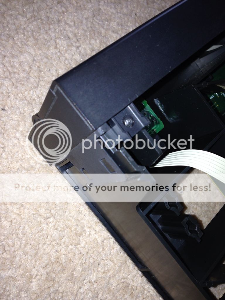
From the top, we need to disconnect the loading motor.


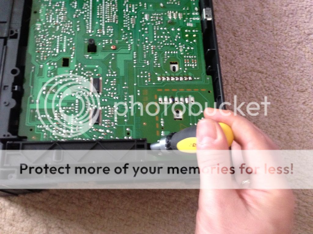
From the back, there are torx screw to undo by the output phono's in the middle and by the mains socket. From the bottom there are torx screw in the PCB and 2 larger black cross heads either side of the transformer to remove. Once these are out there are 2 tabs to press to allow to board to move out. Press the tabs to start the board moving but only move it enough to ensure its mechanically free. There is still a cable to the spin motor and ribbon the laser to disconnect.

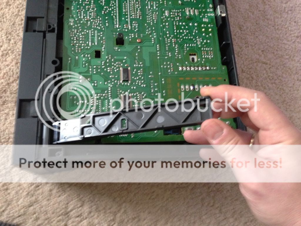
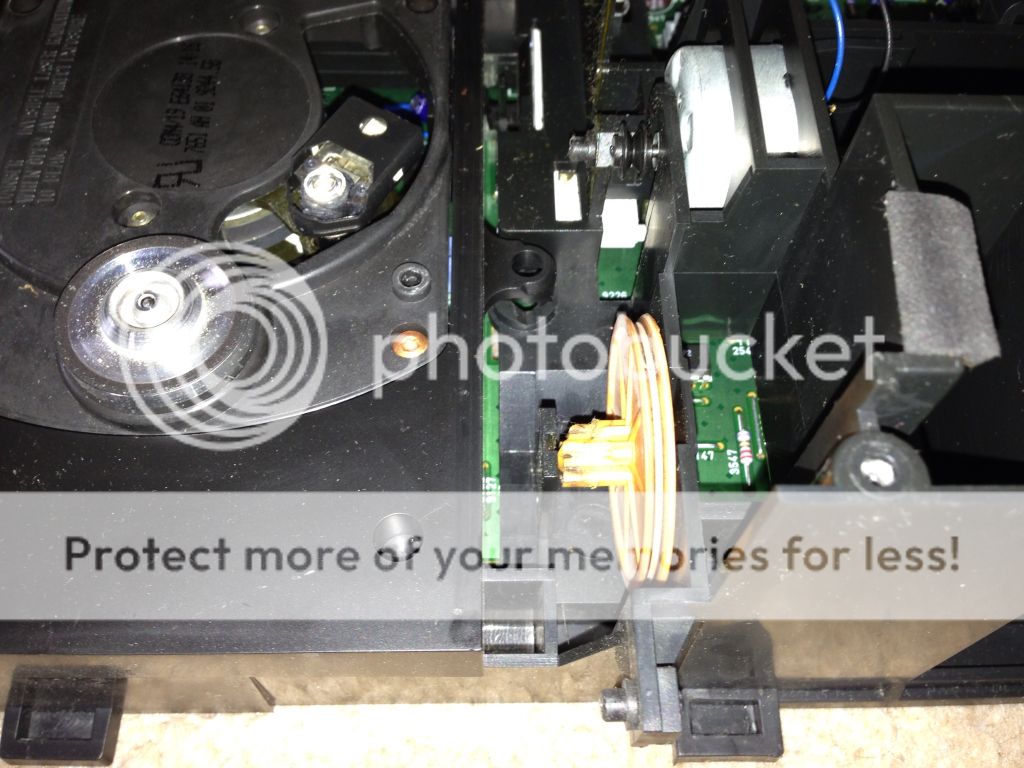
This picture shows 1 of the tabs.


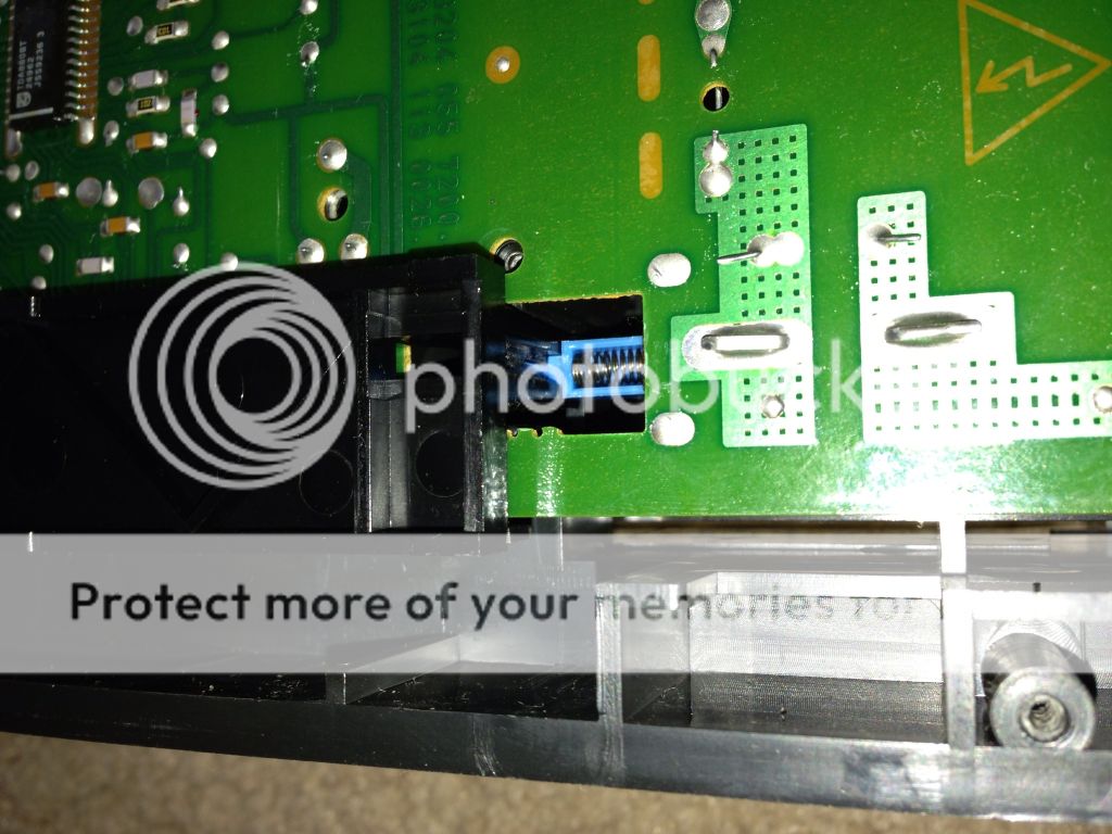
When the board is free, we need to locate the ribbon. You can access the ribbon from the side. The white collar on the plug needs to lift away from the the PCB to release the cable. Its a bit of a fiddle the 1st time you try to do it. Be very careful not to pull on ribbon until the collar releases or you could damage it. Its very fragile! Once release you need to access the spin motor connector from the front. Its got a tab on the PCB side that needs pressing to release the plug.


With both of these released, the board will come out of the player and leave you with this


I would now put all the mechanical bits back together for safe keeping.
You will notice a white mech under the transport. This will just fall out. Make sure you dont loose it because its part of the drawer proximity mechanism!

I've now got the main PCB out. The first thing I noticed is that the transformer runs warm. This suggests to me that its working quite hard. This is a sure sign that things can be improved with bigger transformers. I've yet to decide if I'll take this route due to the likely value of the player after some mods.


Now we can start to identify components and possible upgrades!


The Teardown - Replacing the loading gear (all CDM4/19 )


To get to the cog for replacement and the main board for mods,we need to completely dismantle the player. Same principle applies to most of the CDM4/19 based players by Marantz and Philips.

There are 5 screws in the top cover which we need to remove 1st. 4 cross heads on the side and 1 torx on the back in the middle. Undo all 5 and remove the lid lifting the back of the cover 1st up and backwards.

Next turn the player upside down. We need to remove the bottom cover.
There are 8 torx to remove to release the bottom plate.


Next we need to remove the on/off switch bar. This is done by disconnecting the bar from the actual switch then lifting up and back to remove it from the front panel.


Next we need to remove the front cover from the CD tray. From the top of the player, you can just push the tray out a bit. You need access to the underside of the tray to remove the front of it. There is a tab that needs to be pushed out very gently to allow the front to slide across and off. Should be reasonably obvious from the pictures. The tab is at the top of the 1st 2 pictures.


From the top again, you can now unplug the 2 white plugs from the display and headphones

Now you need to remove the 3 torx screws from the top of the main front panel assembly. Ensure the CD tray is fully retracted inside the player. Release the tabs on each side of the player and release the front forward from the top. once free, it should just lift out from the bottom.


Now you need to remove the CD tray. Lift the clamp mech to the vertical position and just withdraw the tray from the player. You may need to move the clamp up and down in order for the tray to clear the transport and come tight out. 


Now you can see the broken cog which needs to be removed. By applying pressure to the mounting on the transport side, you can move it enough to free the cog......easy!!!


Putting it back is just the reverse! I don't suppose my replacement will be here for several weeks so i'll just keep the screws safe and proceed to remove the main board for mods........TBC

CD52 MKII Mods part 1


This is one that I've not had a play with at all yet. I've had several goes at the CD50 which uses the TDA1541 dac, CD850 and I owned a CD850MKII from new for about 18 years all of which use the later swing arm type laser assembly from philips, the CDM4.

I thought i'd start this thread to show the mods progress and explain some of the rationale behind some of the changes that will be made. I'll lay my cards on the table now, I've no intention of keeping the player at the end and I will offer it up for sale (in the appropriate forum section) for a sensible price that reflects the cost of the parts plus a few beers. I'm not looking to spend hundreds but I do expect to make significant improvements within a reasonable budget.

Hopefully the thread will be informative and therefore my approach acceptable to the community. As previously stated in other threads, I do this because I can and I really enjoy it! If I can fund my obsession by selling at the end of the project then happy days 

There is plenty of information relating to these players on the internet. The player is Pre the KI Signature badge. That doesn't mean "he" wasn't involved! Indeed all of the SE range are his work. From experience I can tell you that in general, the SE versions are mainly about a few capacitor changes and bracing the actual cases. I have read that in some SE models the transformer is constructed using higher quality materials but I cannot confirm this. Certainly in KI models, the mods are SE plus a toroid transformer most likely of a higher VA plus copper chassis plating and a shiny badge!

Since I'm likely to change and improve most of what the SE would offer, I've started with a basic CD52MKII as the only reason I can see for using an SE would be for perception.

I've got hold of a reasonably priced player that works other than the drawer loading cog which is a common problem on all CDM4/19 transports. A replacement made from a more modern plastic is readily available for £6 on ebay. This is one time I'm glad our friends from the other side of the world are happy to 'clone' everything! The original part went out of production many years ago! For a test listen, the drawer can be manually operated. 

I'm not going to washy word audio reviews at every stage of this project but I will give a very brief overview at the start and finish of the project. To start I need to verify that everything work as it should and that there are no actual faults with the player (other than the loading cog). I have a couple of test CD's I know very will with a mix of tracks on them so having listened to them to verify functionality I can also comment generally on the sound. What I will say at this point is that the sound is quote flat compared to what I'm used to. Its quite a warm sound but lacks sparkle and accuracy. Something I'm sure I can improve to a reasonable degree. Don't get me wrong, I'm sure the standard sound would suit many, its just not good enough for me out of the box and I know it can do better.

Here's the player in the flesh during test this morning. I've already removed the offending loading cog and ordered a replacement which will come with a new belt too.


Here's the offending cog. As you can see, its stripped most of its teeth. The theory offered on the internet is that the grease philips used has reacted with the plastic and made it go soft. I can tell you it feels more like hard wax now than plastic although I'm not convinced by the theory about the grease! Having owned an 850MKII from new, I can tell you that you push the drawer to close. This is bound sure to stress the gear as its work ratio means that the motor spins hundreds of times to move the drawer from end to end. just pushing the drawer 1 cm is likely to require the motor to spin 3 or 4 times. This will put far too much pressure on the fragile teeth of the old cog. Armed with this information, even with the new cog, I'd recommend using the play button to close the drawer.


Next up will be some investigative work in the core power supply to see what can be done to improve things immediately before and after the voltage regulators............